Note: All pictures that follow are
"clickable". Clicking on them will show you an enlargement!
A lil' history ...
 You probably have heard about fail-safe switches in the past.
The purpose of these type of switches is to isolate the possibility of the
mechanical switch failing (if switch fails, you get no power to your receiver, a BAD
situation when in the air). The operation of a failsafe switch is designed such that the mechanical switch (normally a DPST slide switch) turns power
"OFF" to your receiver vice turning power "ON". With this type of design,
if the switch contacts fail, the receiver will still be getting it's much needed
power. So, how does this type of "fail-safe switch" work? And how do
you build one? Ah! Glad you asked!
You probably have heard about fail-safe switches in the past.
The purpose of these type of switches is to isolate the possibility of the
mechanical switch failing (if switch fails, you get no power to your receiver, a BAD
situation when in the air). The operation of a failsafe switch is designed such that the mechanical switch (normally a DPST slide switch) turns power
"OFF" to your receiver vice turning power "ON". With this type of design,
if the switch contacts fail, the receiver will still be getting it's much needed
power. So, how does this type of "fail-safe switch" work? And how do
you build one? Ah! Glad you asked!
For my application, not only did I want to design a fail-safe switch, I also
wanted to incorporate a voltage regulator. My need for this was due to the
fact that I wanted to power my receiver and servos using 2 Lithium Polymer
battery cells (nominally, 7.4 volts). Receivers and servo do not like
being powered by this excessive voltage hence you need to regulate it down to
around 5 or 6 volts (my goal was 5.5v). I dug around on the internet, browsing
through various voltage regulator manufacturer webpages and finally came upon a neat 5
pin regulator. The key with this regulator is that it has a Low Drop-Out (LDO),
meaning that the voltage drop (i.e. loss) across the regulator will be minimal, much less than ordinary 78xx/79xx 3-pin regulators. But why does this
LDO regulator have 5 pins you ask? I wondered the same until I started
reading the datasheet. The other pins allow you to control the
output of the regulator (i.e. enable or disable). WOW! Neat, just
what I was looking for. After thoroughly reading the specs (LDO, 3 amp,
with adjustable voltage output, with enable/disable), I started my design.
Design Criteria Summary:
1) Low Drop-Out (LDO) Linear Voltage Regulator (no
switching/buck, etc... too much EMI noise)
2) User-Adjustable output voltage (my need was around 5.25-5.5 volts)
3) Minimal components (small PCB)
4) Deans main battery connection for low loss (as I am using a 2-cell LiPo pack
with Deans mating connector)
5) Integrated heatsink/circuitboard (could also use optional aluminum heat-sink
if max current is required)
6) At least 2 amp current capability (this design is based around a 3 amp LDO
regulator)
7) Fail-Safe Switch Design (outboard switch used to turn regulator OFF, not on)
- If switch fails, Regulator stays ON.
Parts & Tools List
...
1) IC1 = LP3966ES-ADJ (LDO 3amp
Adjustable Linear Voltage Regulator by National Semiconductor)
2) R1 = 10K Resistor
3) R2 = 10K-50K Resistor (for adjusting voltage output, 33K makes output ~5.25
volts))
4) R3 = 1Meg Resistor (pull-up for switch)
5) Cf = 68pF Ceramic Capacitor
6) Cin = 100uF SMD Tantalum Capacitor (min = 68uF)
7) Cout = 47uF SMD Tantalum Capacitor (min = 33uF)
8) Ordinary R/C Switch Harness (i.e. DPDT slide switch) or even a push
on/push off button switch!)
Building Instructions...
A circuit-board makes the design very simple and makes the
assembly quick and neat.
Here is a picture of the kit parts, minus any
connectors/wires.
Included is the PCB, a LP3966 LDO Regulator, a 10K
resistor, a 1 meg resistor, a 33K resistor, a 100uF SMD capacitor, a 47uF SMD
capacitor and a 68pF disc capacitor.
The user must supply connectors such as a servo wire
for powering the receiver/servos and the battery connection (the PCB is made to
mount a Deans male connector).
The first step in building this neat fail-safe
regulator is to solder on the LP3966 LDO regulator. As shown in the
picture to the left, use a clip to hold the regulator onto the PCB (this clip
also dissipates excessive heat which could ruin the regulator) and be certain
the regulator leads line up with the appropriate PCB lands. Apply enough
heat to solder the 5 regulator tabs onto the PCB.
This is what it should look like after soldering the
regulator onto the PCB. Pretty easy. Just be sure you do not use too
much heat as this will ruin the regulator (use a heat sink when ever possible).
Next, solder the main grounding tab of the regulator
to the PCB. Use plenty of heat for this connection (it might take a while
to heat up the large tab,... be patient). Again, use a clip-on heatsink to
dissipate excessive heat (I moved the clip after soldering to show you what it
should look like after soldering). You could even put some conductive
heatsink paste under the regulator if you want.
The next step is soldering on the all important
input and output capacitors (these are SMD versions to cut down on size and
weight). BE SURE YOU ORIENT THEM PROPERLY AS
THESE WILL BLOW UP IF PUT IN BACKWARDS! The lines on each SMD
capacitor indicates the "+" lead (unlike regular radial caps where the line/mark
usually indicates the negative lead). Be very careful to orient them as
shown in the picture (lines point to each other). Again, using the clip,
clamp down each capacitor and solder each lead/end onto the PCB.
Next, place and solder the remaining components from
the other side of the PCB. This includes soldering the 33K resistor, the
10K resistor, the 1M resistor and the 68pf disc capacitor. Bend the leads
over and cut and solder. Orientation is not important for either
component.
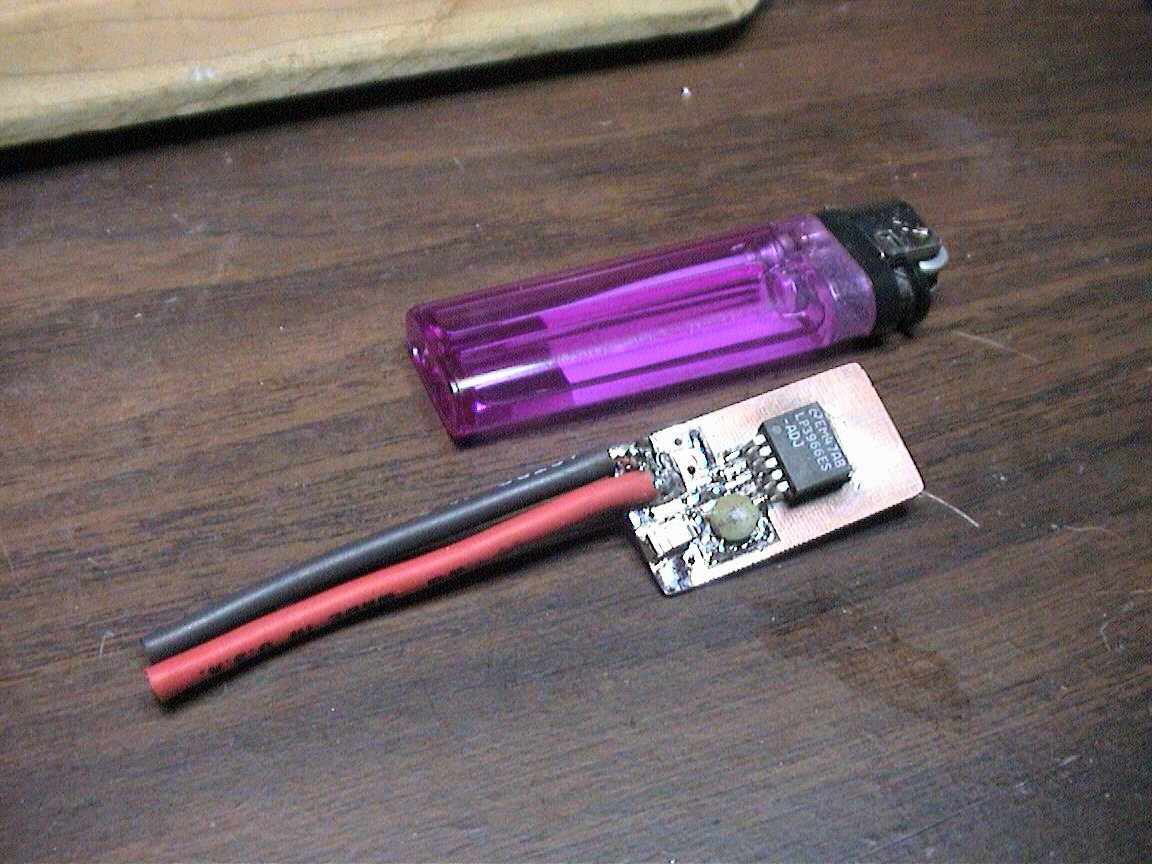
This is what the finished product should look like !
(Notice that in this picture, I used different SMD
capacitors... both are 68uF... I ran out of larger SMD caps for this regulator..
but it still works fine).
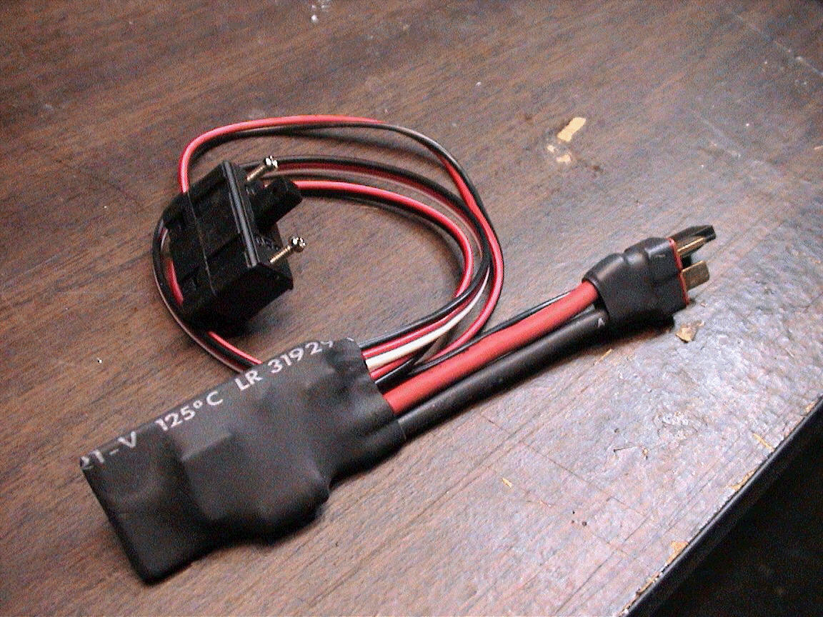
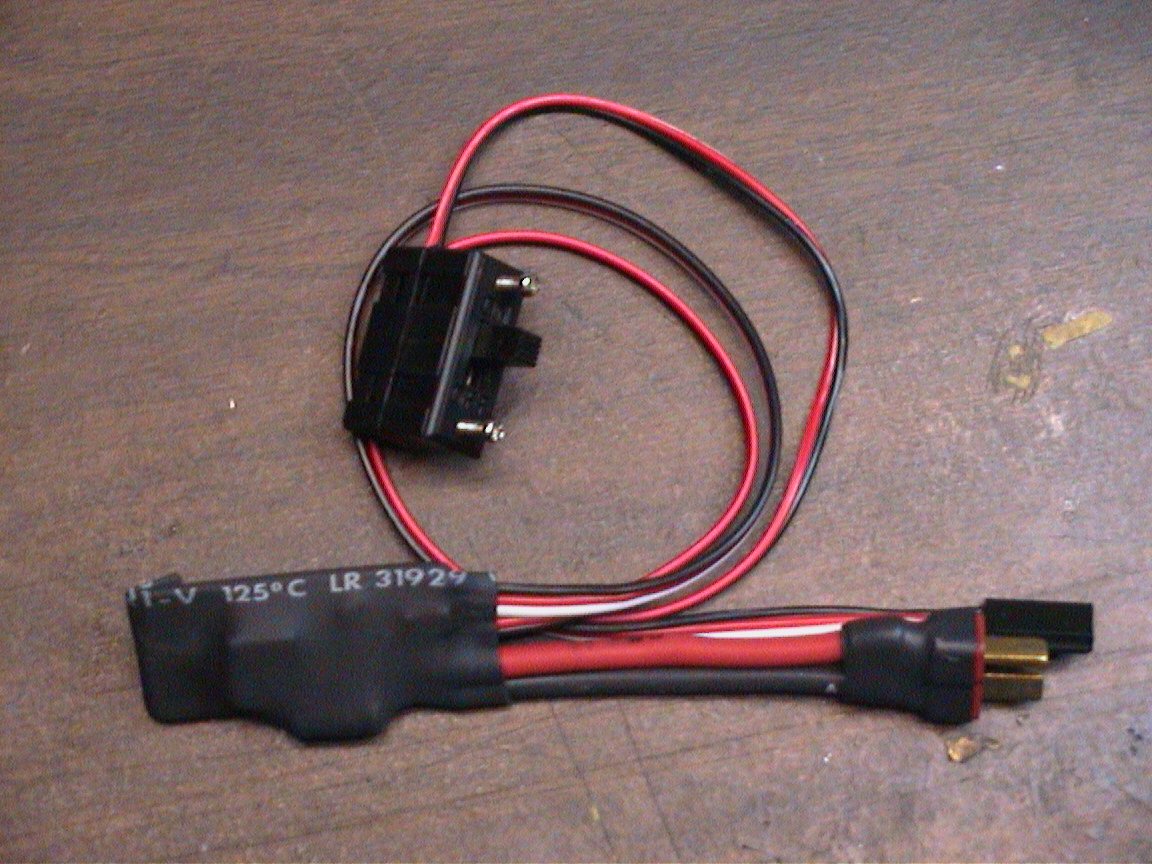
The final step before testing is to attach your
connecting leads for both the source battery (I usually use a Deans connector
soldered to the PCB as shown below) and a servo-like wire that is used to
connect to your R/C gear (receiver/servos).
Please not the polarity of both the input
(IN=battery) and output (OUT=to R/C receiver) PCB connections.
After connecting these leads, connect the fail-safe
regulator to your battery and test the output of the regulator to be sure it is
outputting roughly 5.25 volts (Test this before
connecting it to your R/C gear else you could possibly ruin your gear if the
regulator is not functioning properly).
If all appears ok, test it with your R/C gear.
ADDING THE MECHANICAL SWITCH
The last thing you will have to do, in order to use
the fail-safe feature, is to connect a normally open switch to the regulator PCB
(larger PCB holes just above one of the SMD capacitors. With out this
switch connected, the regulator will always be ON. The switch (when
closed) will actually turn the fail-safe regulator OFF (hence, the fail-safe
feature if the switch craps out). The Pull-up resistor (R3) is set to 1
Meg ohm, such to limit the current consumed when the switch is closed (regulator
turned OFF).
Please Note: When
using this fail-safe switch feature, even in the OFF position (mechanical switch
is closed), the regulator circuitry can draw a slight amount of current (roughly
4-10ma). It is highly recommended that you remove the battery when you do
not plan to use it for days at a time.
Testing and Operation Instructions...
After building this regulator, be sure to measure
the output and verify it is as designed (5.25 volts, using the resistors
described above) before connecting it to your R/C gear.
If you want to change the output voltage, calculate
the new resistor value using the formula here:
If R1 is always held at 10K, you can calculate the
value of R2 for any output voltage (Vout).
For an output of roughly 5.25 volts, R2 calculates
to be roughly 33K
Additional Notes...

Earthmen
Productions
© Dec-00-Mar-12
