Assembly Instructions
User's Manual
BUY ONE NOW! VIDEO!
 CLICK HERE to see a video of the Mini-Beacon on a R/C
Helicopter!
CLICK HERE to see a video of the Mini-Beacon on a R/C
Helicopter!
A lil' history ...
 This
project, called "Mini-Beacon", is a miniature
programmable LED Flasher that is based around the PIC microcontroller.
This project grew out of an idea and recommendation posted on
RunRyder.com. The Mini-Beacon basically
simulates the light emitted from a rotating light beacon such as those used in
older police cars and fire engines. As seen from the observer's
perspective, as a
This
project, called "Mini-Beacon", is a miniature
programmable LED Flasher that is based around the PIC microcontroller.
This project grew out of an idea and recommendation posted on
RunRyder.com. The Mini-Beacon basically
simulates the light emitted from a rotating light beacon such as those used in
older police cars and fire engines. As seen from the observer's
perspective, as a real rotating beacon revolves, a dim light slowly ramps up brighter and brighter
until a flash is seen (light facing directly toward observer), then as it
continues rotating, the light slowly dims out and a pause is observed until it
repeats over and over again. Well, the "Mini-Beacon" simulates this exact
effect! The user can also choose 1 of 12 different flash patterns to be
repeatedly displayed. These patterns include slow, medium and fast
rotational beacons (ramp-up & ramp-down speeds), and 3 different selectable
flash patterns (single, double and triple flash). This selection is made
by simply shorting a small jumper on the driver board. This setting is
retained in memory so that every time the "Mini-Beacon" is powered up, it will
display this pattern.
real rotating beacon revolves, a dim light slowly ramps up brighter and brighter
until a flash is seen (light facing directly toward observer), then as it
continues rotating, the light slowly dims out and a pause is observed until it
repeats over and over again. Well, the "Mini-Beacon" simulates this exact
effect! The user can also choose 1 of 12 different flash patterns to be
repeatedly displayed. These patterns include slow, medium and fast
rotational beacons (ramp-up & ramp-down speeds), and 3 different selectable
flash patterns (single, double and triple flash). This selection is made
by simply shorting a small jumper on the driver board. This setting is
retained in memory so that every time the "Mini-Beacon" is powered up, it will
display this pattern.
If this was not enough, the "Mini-Beacon" also
allows you to run it in "free-running" mode (connect battery and it repeatedly
flashes), or you can control it (on/off) using a spare receiver channel on your
R/C receiver (you can use a transmitter stick or switch). The
setting is accomplished using two small jumpers on the board and is described
below in detail. Additionally, and most likely most important... you can
also control the Mini-Beacon using a "Mini-Flash" Controller by simply plugging
them together!
Design Criteria Summary:
1) Design a simple, cheap but effective "Rotating
Beacon" simulator/driver
2) Design so user can easily choose 1 of 12 flash patterns
3) Lightweight and simple to build (DIY)
4) Circuit powers off of existing R/C servo connector
5) Use servo signal to turn on or off the flashing Beacon effect
6) Powers a bright LED (around 600mA max... a one (1) watt Luxeon looks great!)
7) Listen to customers and their needs! :)
Parts & Tools List
...
1) One
(1) PIC 12F629 Chip (preprogrammed with Mini-Beacon code)
2) Two (2) 10K ohm resistors
3) Two (2) 2.2K resistors
4) One (1) Servo Lead/Pigtail wire for Mini-Beacon
5) Four (4) 2 pin header (male) - 3 for Jumpers, 1 for LED/output
connector
6) One (1) 2N2222 or PN2222A NPN Transistor
11) One (1) two-row header (mating connector for Mini-Beacon output
pins)
12) One (1) piece of heat shrink tubing for assembly
13) Two (2) Shorting Jumpers (one for run mode and the other for programming)
Note: Customer is
responsible for supplying LEDs and connecting wires...
LEDs are sold separately
in the DIYRC webstore... CLICK HERE to view them!
Building Instructions...
* MINI-BEACON BUILDING INSTRUCTIONS *
(Sorry, I am not selling these in
kit form... I'd rather build, test and sell)

Testing and Operation Instructions...
Download the Mini-Beacon User's Manual below (in PDF format... Adobe reader
is required)
*
MINI-BEACON USERS' MANUAL
*
The web version
of the manual is shown below:
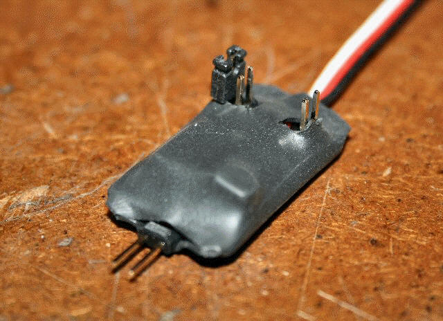
 The
Mini-Beacon controller has a servo cable which can either be plugged into a
spare channel on your Radio Control receiver (Rx) or it can simply be connected to a 5-6 volt
power source. Opposite of this servo cable lies a two pin connector
(inline with board) that is used to connect your beacon LED. The onboard
output driver/transistor is capable of providing around 600mA to a connected load.
A typical 5mm LED draws 20mA while a 1 watt Luxeon emitter draws an average of
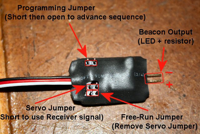
350mA. 3 sets of jumpers/pins located on the Mini-Beacon are used to
either set the flash pattern (1 of 12), set the servo control function, or allow
the controller to free-run. First thing you will obviously need to do is
connect an LED to the Beacon output pins (see picture above, observe polarity).
Be sure to use the proper series current limiting resistor inline (series) with
one of the LED leads (typically 56-120 ohms).
The
Mini-Beacon controller has a servo cable which can either be plugged into a
spare channel on your Radio Control receiver (Rx) or it can simply be connected to a 5-6 volt
power source. Opposite of this servo cable lies a two pin connector
(inline with board) that is used to connect your beacon LED. The onboard
output driver/transistor is capable of providing around 600mA to a connected load.
A typical 5mm LED draws 20mA while a 1 watt Luxeon emitter draws an average of
350mA. 3 sets of jumpers/pins located on the Mini-Beacon are used to
either set the flash pattern (1 of 12), set the servo control function, or allow
the controller to free-run. First thing you will obviously need to do is
connect an LED to the Beacon output pins (see picture above, observe polarity).
Be sure to use the proper series current limiting resistor inline (series) with
one of the LED leads (typically 56-120 ohms).
There are two ways you can operate the Mini-Beacon
controller. You can either set it up so it's in "free-running" mode
(apply power, and it flashes continuously until power is removed), or you can
connect it up to a spare R/C receiver servo channel and control (on/off) the flashing pattern of the
beacon using a stick, slider or switch on your transmitter (aka Servo Control
Mode). The Mini-Beacon has two jumpers that allow you to set these two
functions (labeled "Servo Jumper" and "Free-Run" on the picture above.
Only one of these jumpers should be connected at one time.
Servo Control Mode
If you want to be able to turn the beacon effect on & off using your R/C gear,
you will need to attach the supplied push-on jumper to the pins labeled "Servo
Jumper". This allows the servo signal from your Rx to be read by the PIC.
Note: No jumper and/or short should be across the
"Free-Run" pins.
Now, when you plug the Mini-Beacon into your
receiver, not only does it gets its power, but it also reads the servo signal
output signal from the receiver's servo channel and
either turns on or off the beacon effect. The PIC is pre-programmed to switch
on at roughly 60%. If you use a switch to control this function, you might
have to reverse that channels servo function on your transmitter in order to get it
to work to your satisfaction (i.e. configure on/off position of switch). Also, be sure
the R/C channel you are using has its "end-points" set to at least 100% on the
transmitter.
Free-Running Mode
If you want to allow the Mini-Beacon
to run all the time when ever powered up, you need to do two things (referring
to picture above):
1) Disconnect any jumper/short attached to the pins
labeled "Servo Jumper" if it is connected.
2) Apply a push-on jumper across the pins labeled
"Free-Run"
Now, every time you power up the Mini-Beacon, it
will begin flashing, and continue so as long as power is applied. You can
still plug the Mini-Beacon into your receiver for power, but the servo control
function will not work.
 Controlling
the Mini-Beacon with your "MINI-FLASH" !
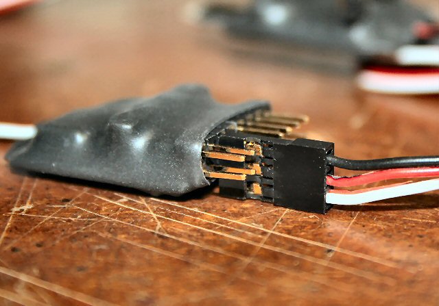
Controlling
the Mini-Beacon with your "MINI-FLASH" !
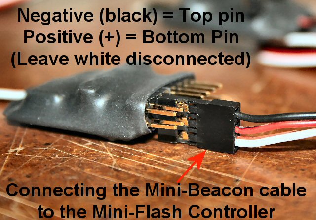
You also have the cool option of controlling (on/off) your Mini-Beacon
using a channel on your Mini-Flash. This is accomplished by first
setting up the Mini-Beacon so it's in free "running mode" (no jumper across "Servo
Jumper", and a jumper across "Free Run" pins). You can now take the
Mini-Beacon servo/power lead and plug it directly into a channel on your
"Mini-Flash" controller in order to receiver power when the Mini-Flash
channel is active. Be certain that you plug it on correctly, the
black lead should connect to the top pin on the Mini-Flash, while the red
lead connects to the bottom pin on the Mini-Flash. The white lead on the
Mini-Beacon should connect to nothing (hangs down a little below Mini-Flash
board).
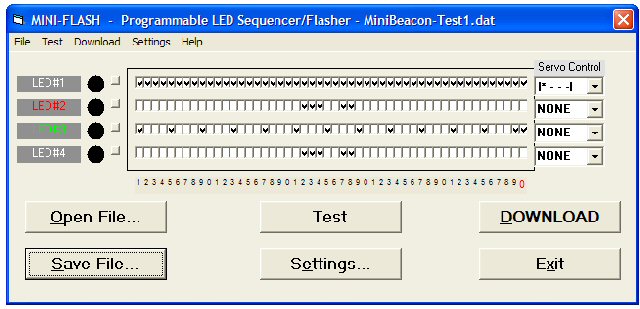 (Click
on picture to the left for an enlargement of what the Mini-Flash programming
software would look like to control the Mini-Beacon).
(Click
on picture to the left for an enlargement of what the Mini-Flash programming
software would look like to control the Mini-Beacon).
Now, set up a Mini-Flash channel (#1 in this
example) such that all 50 events have a checkmark in every location. Set
the Servo Control for channel #1 such that it is only ON for 0-1/4 throttle
("*---"). Now, when the Mini-Flash channel is High or ON
(only between 0 and 1/4 throttle), it applies power to the free-running Mini-Beacon, allowing it to flash
its preset pattern. When the Mini-Flash channel turns off, so does the
Mini-Beacon. You can then set up the Mini-Flash such that the channel
events (all 50) are selected or check-marked (left to right), and then you set
the servo control for the stick position you want for that channel to activate.
If you are using a switch on your transmitter to control this channel the
Mini-Beacon is plugged into, simply set the servo control to "**--".
Cool or what?
Programming
& Operating the "Mini-Beacon"...
The "Mini-Beacon" can be programmed to display 1 of
12 different flashing sequence patterns stored on the PIC. To change the
pattern, perform the following steps:
1) Apply power to the Mini-Beacon and be sure it is
flashing its programmed pattern.
2)
While the pattern is flashing, continuously short the programming jumper (two
pins shown towards the top/left on drawing) with either the supplied jumper or a
piece of conductive metal (coin, paper clip, screw/nail, etc...)
3) Soon after you short these pins together, you
will see the LED glow constantly bright. While it is glowing steadily,
remove the short/jumper and you will see the controller quickly flash a certain
number of time before continuing its rotating beacon effect. The number
of flashes seen here indicates the pattern number it is now using and
displaying. The 12 different patterns are shown below:
1) Slow Ramp-up, Flash, Slow Ramp-down
2) Slow Ramp-up, Double-Flash, Slow Ramp-down
3) Slow Ramp-up, Triple Flash, Slow Ramp-down
4) Med. Ramp-up, Flash, Med Ramp-down
5) Med. Ramp-up, Double-Flash, Med. Ramp-down
6) Med. Ramp-up, Triple Flash, Med. Ramp-down
7) Moderate Ramp-up, Flash, Moderate Ramp-down
8) Moderate Ramp-up, Double-Flash, Moderate Ramp-down
9) Moderate Ramp-up, Triple Flash, Moderate Ramp-down
10) Fast Ramp-up, Flash, Fast Ramp-down
11) Fast Ramp-up, Double-Flash, Fast Ramp-down
12) Fast Ramp-up, Triple Flash, Fast Ramp-down
4) Continue applying and removing the jumper
(following steps 2-3) until you selected the pattern you like. When you
are satisfied, you are done! Every time you now power up the controller,
it will use this pattern you have selected.
NOTE:
Recent
Mini-Beacons I have sold also have another hidden function that allows you to
quickly reset the pattern to Pattern #1, rather than having to cycle through all
the patterns using the jumper/power numerous times. With the Mini-Beacon
un-powered, connect the programming jumper and then power up the Mini-Beacon.
You will see the LED glow steady and will do so until you remove power, so
remove power. Remove the jumper and re-power the Mini-Beacon. It
should now be set to program #1, regardless of its previous pattern setting.
A video of these patterns can be seen by clicking HERE!
WANT TO BUY A PRE-ASSEMBLED & TESTED
MINI-BEACON CONTROLLER?
Mini-Beacon Controller (+ mating LED connector
not shown)
(Assembled & Tested)
CLICK HERE TO
BUY ONE NOW !
LIMITED SUPPLY !
Mini-Beacon Controller -
Pre-Programmed PIC Only
(This is for one pre-programmed PIC only... no other
parts)

CLICK HERE TO BUY ONE NOW !
LIMITED SUPPLY !
MINI-FLASH FAQ
Q1. How do you compensate for
differing forward voltages and current drawn by differing LED's?
A1. Ah.... good question....
The input voltage to LEDs is all not that important (usually 5v is fine for
all). It is the current that you push through the LED that is important, as you
do not want to drive them with too much current. You usually always need to put
a series resistor inline with one of the LED leads such to limit the current. I
use a neat calculator, I even have a link for it on my webpages. You really need
to know the specs on the LEDs, particularly the LEDs rated current (typical 5mm
LEDs run around 20-25 milliamps). Here's the calculator:
http://linear1.org/ckts/led.php
You simply enter the supply voltage (in the
controller's case, 5 volts), the LEDs forward voltage (this varies from LED to
LED) then enter the rated LED current (typically 20-25 milliamps). Then hit the
"find R" button and the program calculates the resistor value you need for that
LED (typically a 68-120 ohm resistor is required). Be careful also as there
exists some LED that already have the series resistor incorporated in the LED
(not all that common though). Once the resistor value is determined, I
usually then solder it to the end of one of the LED leads. The wires then
leading from this LED assembly is then connected directly to the controller
using a miniature machine-pin female socket (I will provide at least 8 with
every controller). Putting the series resistors on the PCB would take up
space (unless they were SMD maybe).
Additional Notes & Pics...
